MODELLING OF QUADCOPTER ON SOLIDWORKS
INTRODUCTION
In this project, we are to learn the entire modeling of a Quadcopter using SolidWorks for modeling and SolidWorks Visualize for rendering.
The different components of the Quadcopter we deal with are:
1. Body
2. Distribution Board
3. Battery
4. Fan Blade
5. Spider Top
6. Spinner
7. Pillar
8. Electrical Unit 1
9. Electrical Unit 2
10. Spider Arm
11. Connector
12. Spacer
13. Motor
1.Flowchart

2.Tools / Features Used
1.Extrude Boss: Extrude Base is the feature that helps us to convert 2d drawings into 3d by adding thickness in the 3rd dimension. After completing the sketch select Extruded Boss/Base on the Features toolbar. The Boss-Extrude feature button will prompt you to set parameters as shown in the figure where we have options to set depth, direction, and plane from which extrusion has to take place, etc.

2. Revolved Boss Feature: It is used to create a solid 3D model around an axis. You can revolve the sketch around an axis to add materials to it. After completing the sketch, keeping the sketch selected we revolve the sketch about a particular axis or reference axis.

3. Sweep Boss / Sweep Cut: It is used to add or remove material from a solid model or part by sweeping a completely closed profile along a path. Swept Boss or Base-up solid material to the body of design and Swept Cut removes material from the body of the design.

4. Fillet: Fillets are used to round off edges and/or corners. Fillet adds or removes material, depending on whether the edge is internal or external in order to convert edges or corners to rounded ones. There are manual fillet and fillet expert options that will be useful depending upon the complexity of the model, or no of models we have to add fillet.

5. Linear Pattern/Circular Pattern/Curve driven Pattern: It is used to create multiple instances of one or more features that you can space uniformly along one or two linear or circular paths. In a linear pattern we have to select the linear path pattern that needs to be followed, In a circular pattern, we have to select the circular path the pattern needs to be followed. In a curve-driven pattern, we have selected the curve along which pattern has to be followed.

6.Extruded Cut: Extruded cut typically refers to a feature in 3D modeling software, often used in computer-aided design applications. This feature allows you to remove material from a 3D object by creating a cut or void that extends through the object.
7. Mirror: It allows us to duplicate features just like the mirror image. We can mirror the features along a plane, axis, face, reference geometries, etc. We also have the option to mirror patterns, bodies, multi bodies which make the designing a lot easier.
8. Reference Geometry: Reference geometry defines the shape or form of a surface or a solid. Reference geometry includes items such as planes, axes, coordinate systems, and points.
9. Mate: Mates create geometric relationships between different parts we made. It helps to create different mates with relation of concentric, parallel, perpendicular, tangent, etc.

3. Parts of Quadcopter
1.Body
In the process of creating the body, a combination of extrude boss and extruded cut techniques was employed. The utilization of extrude boss involved adding material to the design, while extruded cut was used to remove specific sections, resulting in the desired form. Additionally, fillets were incorporated during this crafting process to introduce rounded or beveled edges, contributing to a more refined and aesthetically pleasing final product. This comprehensive approach, combining various techniques, allowed for the precise manipulation of the body's geometry and the achievement of a well-defined and polished appearance.

2. Distribution Board:
The creation of the sketch involved the utilization of sketching tools and modifying techniques to outline and refine the desired design. Following the sketching phase, the next steps involved employing both extruded boss base and extrude cut features. Extruded boss base was applied to add material and give three-dimensional depth to specific areas of the sketch, shaping the overall form. On the other hand, the extrude cut function was used to remove material, creating voids or indentations in accordance with the established sketch. This combination of sketching, modifying tools, and the strategic use of extruded boss base and extrude cut contributed to the intricate and precise development of the final design.

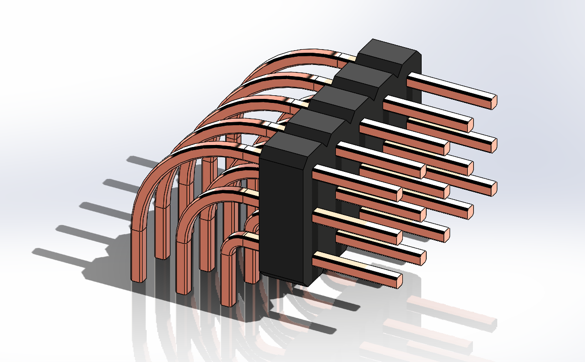
3. Electrical Units:
The creation of the electrical units involved a multi-faceted approach, utilizing several commands in the design process. The sweep command was employed to generate intricate shapes by guiding a profile along a specified path. Extruded boss base was utilized to add material and form the foundational structure of the units. The incorporation of fillets played a crucial role in refining the edges and surfaces, enhancing both the visual appeal and structural integrity of the components. Furthermore, the linear patterns command was employed to replicate certain features or elements in a consistent manner, ensuring uniformity and efficiency in the design.

4.Spider Arm:
The initial step involved the application of the "extruded boss" command, wherein material was added to sculpt the primary structure of the arms. This allowed for the formation of the basic shape and dimensions required for the spider arms. "extruded cut" command was then employed. This command facilitated the removal of specific sections from the initially shaped structure, Fillets were strategically applied to round off edges and corners, not only contributing to a more polished and visually appealing appearance but also serving functional purposes.

5. Spider Top:
This part was crafted through the utilization of extrude boss base, extrude cut, and fundamental sketching techniques.

6. Motor:
To model the motor, we employed the revolve command for shaping and the extruded cut command for precision. These commands allowed us to create intricate designs by revolving profiles and making specific cuts, contributing to the efficient and accurate construction of the motor components.

7. Fan Blade:
The fan blade design incorporated extruded boss base and circular pattern techniques. Additionally, extruded cut was employed to create the central hole, while fillets were added for refinement. These methods collectively contributed to the precise modeling of the fan blade.

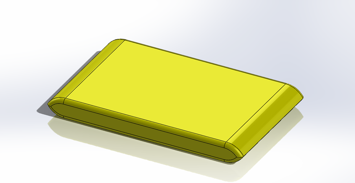
8 & 9. Connector and Battery:
The essential electrical components, such as connectors and batteries, are crafted using techniques like extruded boss base and fillets. These tools contribute to the precise shaping and refinement, ensuring the effective functionality of these crucial elements in electrical systems.

10. Spinner:
This component, integrated with the motor, is crafted using tools such as extruded boss base and cut.which helps in spinning the fan blade.

11 & 12. Spacer and Pillar:
Spacer and pillar, essential for supporting major components in this model, were crafted using tools such as extruded boss base, extrude cut, and revolve.


4. Assembly
In the initial phase of the assembly process, the distribution board is introduced into the assembly workbench. Following this, a fixation process is undertaken to secure its position within the assembly. Subsequently, two electrical units are imported and affixed onto the main body. This attachment is meticulously achieved through the implementation of coincident mates, ensuring precise alignment. Distances beneath the units are carefully managed for optimal spacing. To further enhance the structural integrity, a spacer is introduced beneath the units. The spacer placement involves the application of coincident and concentric mates, creating a stable foundation. A circular pattern is then applied to replicate this spacer configuration.
The main body, serving as the foundation for the assembly, is introduced beneath this intricate arrangement. A coincident mate is utilized to seamlessly integrate the body with the existing components, establishing a cohesive structure. This careful alignment is crucial for the proper functioning and aesthetic cohesion of the entire assembly.
Upon the foundation of the body, the spider arm is strategically positioned. The incorporation of coincident mates ensures a snug fit, promoting a seamless integration into the assembly. At one end of the spider arm, components such as the motor, spinner, and blade are affixed. This attachment is achieved through the implementation of concentric and coincident mates, ensuring the precise alignment of these vital elements. On the opposite end of the spider arm, a connector is introduced. The placement involves the utilization of coincident and parallel mates, securing its position with accuracy.
Proceeding with the assembly, the spider top is positioned at the uppermost section of the assembly. This top section serves as the platform for the placement of the battery, a pivotal component within the overall structure. At the terminal ends of the spider arm and its associated components, a circular pattern is employed. This duplication process ensures uniformity and balance in the assembly's design.
Throughout the assembly process, careful consideration is given to the selection of nuts and bolts. These crucial fasteners are sourced from the design library, selected based on their compatibility and appropriateness for the specific requirements of the assembly. Their strategic placement and secure attachment contribute to the overall stability and reliability of the assembled structure.
In summary, the assembly of this complex structure involves a systematic and meticulous approach. Each component, from the distribution board to the spider arm and its associated elements, is thoughtfully integrated using a combination of mates and patterns. The careful placement of nuts and bolts from the design library further ensures the structural integrity and functionality of the assembly. This detailed assembly process not only results in a functional unit but also showcases the precision and expertise applied in the creation of this intricate design.

5. Rendering
The SolidWork visualizer is a much more realistic tool for rendering. We have to import the assembly file to the visualizer. Wide options to add environment appearances, color, camera, brightness, shadows, etc. Adjusting the view, perspective, changing the appearances of the model and different environments for making different renders. High-quality renders take time to get completed in SolidWork visualize and it gives high quality rendered images of quadcopter in plain background at the end.

THANK YOU!
